We came a very respectible 10th in the Robo-Sumo competition,
Our circuit, very neat, was kept to its most simple.
Using only one colour sensor, located near the front of the robot, as we saw no need for more as this would leave more to go wrong, and our robot had no reverse in the code.
Here is the final code we decide to use for the main competition:
//The Resistor
//08/05/2014
//Robo-Sumo
//Created By Andrew East

#include <xc.h>
#pragma config OSC=INTIO67,MCLRE=OFF,WDT=OFF,LVP=OFF,BOREN=OFF
int state = 0; // start in state 0
float distance; // distance in cm
float get_distance(); // function to measure distance

int main(void)
{
         TRISD = 0b11110000;
         TRISC = 0b11111111;

	while(state == 0) //state 0 is all motors switched off (delay before start), then change to state 1
	{
		LATDbits.LATD0 = 0;
		LATDbits.LATD1 = 0;
		LATDbits.LATD2 = 0;
		LATDbits.LATD3 = 0;
		Delay10KTCYx(225);
		Delay10KTCYx(225);
		state = 1;
	}
	while (state == 1) // state 1 is turn left while searching using ultrasonic sensor
	{
		LATDbits.LATD0 = 0;
		LATDbits.LATD1 = 1;
		LATDbits.LATD2 = 0;
		LATDbits.LATD3 = 1;

		distance = get_distance(); // check distance

		if(distance < 30) // if distance is less than 30 change to state 2
		{
			state = 2;
		}
	}

	while(state == 2) // state 2 is motors start off forward to push
	{
		LATDbits.LATD0 = 1;
		LATDbits.LATD1 = 0;
		LATDbits.LATD2 = 0;
		LATDbits.LATD3 = 1;

		if(PORTDbits.RD5 == 1) // if colour sensor reads white change to state 3
		{
			state = 3;
		}

		if(get_distance() > 30) // if distance greater than 30 change to state 1
		{
			state = 1;
		}
	}
	while(state == 3) // state 3Robot turns left for a certain amount of time using delay
	{
		LATDbits.LATD0 = 0;
		LATDbits.LATD1 = 1;
		LATDbits.LATD2 = 0;
		LATDbits.LATD3 = 1;
		Delay10TCYx(25);

		if(PORTDbits.RD5 == 0) // if colour sensor reads black return to state 1
			{
				LATDbits.LATD0 = 0;
				LATDbits.LATD1 = 1;
				LATDbits.LATD2 = 0;
				LATDbits.LATD3 = 1;
				Delay10TCYx(25);
				state = 1;
			}
	}

}

float get_distance() // function to measure distance using ultrasonic sensor
{
	float d = 0;

	// send pulse to trigger on ultra-sonic sensor
	LATDbits.LATD7 = 1; // send a signal out high
	Delay10TCYx(5); // 200us delay
	LATDbits.LATD7 = 0; // send a signal out low

	while(PORTCbits.RC0 == 0); // wait for start of echo pulse

	while(PORTCbits.RC0 == 1) // once echo returns high, enter loop, counting d
	{
		Delay10TCYx(5); // 200us delay
		d = d + 1;
	}

	d = d * 3.4; // In air, sound travels 3.4cm in 200us (scaling factor)

	return d;
}
The HC-SR04 Ultra-sonic distance sensor works by sending out an ultrasonic wave from trigger terminal and measuring the delay before the signal is measured from the echo terminal, while supplying vcc with a constant 5v and a ground wire connected also.
The longer the returning waveform the further the object is away.
The Timing diagram is shown below. You only need to supply a short 10uS
pulse to the trigger input to start the ranging, and then the module will send out
an 8 cycle burst of ultrasound at 40 kHz and raise its echo. The Echo is a
distance object that is pulse width and the range in proportion .You can
calculate the range through the time interval between sending trigger signal and
receiving echo signal. Formula: uS / 58 = centimetres or uS / 148 =inch; or: the
range = high level time * velocity (340M/S) / ; it is suggested to use over 60ms
measurement cycle, in order to prevent trigger signal to the echo signal.
HC-SR04 Ultra-sonic sensor wave-form output,
whilst sliding an object closer and further from the the sensor.
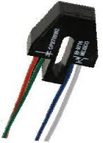
For our robot we are using the OPB704 infra-redrelective sensor.
This sensor has both an infra-red emitting diode and a infra-red detecting photo-transistor together in one plastic unit.
When the sensor is on a dark colour there will be a high voltage (5v) going to the controller, so when its on a light colour its produces a lower voltage (0-1v)
For this reason we decide not to use the sensor on an analogue input but instead opted for a digit input.
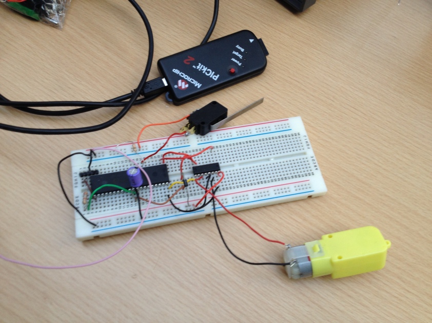
This is the circuit we used in order to control the motor.
From here we researched which motors would be most suited and started to sketch drawings of our robot.
Hello and welcome to my blog, through-out the semester I will write in my blog recording how my team design and I build and programme a robot to enter in robosumo at the end of the semester. First we are to design a robot to run in a race to a wall and back to park on a black strip.
So far we have been researching for the design process of our robot for race to wall competition.